Significant investment and energy is placed on optimizing plastic part design for manufacturing and assembly. Injection molding simulation packages, such as Autodesk Moldflow, are often used to help drive decisions regarding nominal wall thickness, rib and boss design, and snap fit optimization. However, the analysis is often limited to only looking at the filling pattern in the cavity alone, without consideration of the runner design and how it might influence the mold filling pattern in the mold and the quality of the parts. When we look at why we select injection molding as a technology it is often so we can mass produce dimensionally stable components at an economical price. Therefore, when we move to mold design and looking to scale up manufacturing, we often look at ways to increase capacity without significant investment. This objective is typically achieved by either increasing the number of cavities we include in our mold design or by designing a family mold that can manufacture several different components during the same molding cycle, Figure 1. This second method is often referred to as a family mold in the injection molding industry. Either way it is important to optimize the runner system to help ensure we are producing quality parts. Simulation software like Autodesk Moldflow can help us quickly optimize our runner and gate sizing and design so we can get good parts and a wider processing window.
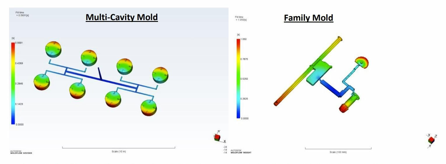
Figure 1: The efficiency of manufacturing can be improved by increasing the cavitation, or by grouping assembly components in the same (family) mold.
When Does it Make Sense to Use a Family Mold?
While to many it may seem like an unnecessary complication to manufacture different parts in the same mold, at the same time, the decision to utilize has many practical implications. Manufacturing different components in the same mold can benefit by:
1. Reducing overall component and assembly cost by reducing mold set up and manufacturing cost.
2. Maintaining similar coloring/part aesthetics in mating components for improved assembly aesthetics
3. Minimizing work in progress (WIP) components, and help with secondary operations like welding and automated assembly.
Therefore, simply by using a family mold, the company can help save money while potentially offering improved part and assembly quality.
What Do I Need to Consider When Designing a Family Mold?
The requirements for a family mold do not really change from those of a conventional mold. We still want to maintain similar principals where we fill the mold uniformly during injection, pressurize the cavity uniformly during packing, and cool the part uniformly during the cooling phase of the project. In short, we want to maintain uniform pressure and temperature conditions during the molding cycle to help maintain high part quality. In order to achieve these goals the mold designer will want to develop a runner system that will help us fill each cavity uniformly.
Part Volume Differences Between Cavities
Commonly in family molds the components that are manufactured together have different part volumes. Therefore, if we simply put the components in the same mold together and make the runners and gates the same size the component with the smaller part volume will likely fill earlier and pressurize while the other cavity is finished filling (Assuming each component has the same wall thickness), Figure 2. This filling imbalance can lead to a pressure spike at the end of fill that can lead to non-uniform shrinkage of components that can cause
alignment issues, flashing or sink mark development, and a narrower process window. All of these issues can increase the cost of our component by increasing the scrap rate, or requiring the use of an operator to remove the flash or visually inspect the parts.
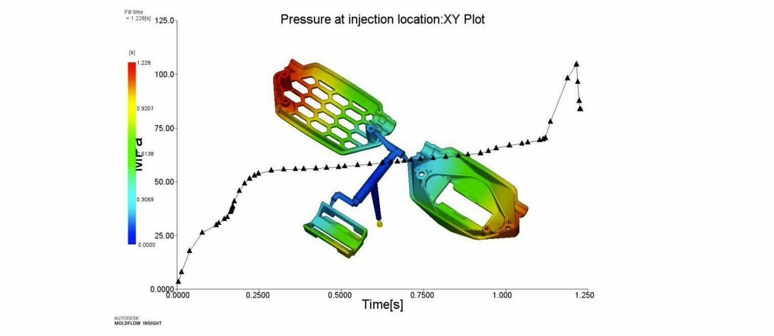
Figure 2: By not optimizing the runner system, the filling of the cavities will be unbalanced and will yield to higher injection pressures and smaller processing windows.
Runner Size and Length
Therefore, with family molds we want to consider the path the molten material needs to take as it is injected from the injection unit into the mold cavities. For molds that utilize a cold runner this control of the flow to the different cavities is often achieved by either varying the size of the runner channel, or by varying the flow length the polymer needs to take to reach the cavity. Since injection molding is a pressure driven process, we can either reduce the size of our flow channel (Runner) or increase the length of the runner to the smaller cavities so the material will preferentially fill the larger cavities first. As Equation 1 highlights, a change in runner radius (diameter), r, has a much more significant effect on our flow resistance as compared to a change in the runner length, L. Because of this sensitivity, it is preferred to balance the filling pattern of the runners rather than the gates. By selecting to use the runners for balancing the filling pattern of the mold, we can minimize the influence of fill irregularities from inconsistent machining or burning of the runner system. If we attempt to use the gate size alone to address any fill imbalance, we minimize the amount of time we influence the molten material and increase our sensitivity to any dimensional inconsistencies in the gate. Therefore, we are more likely to have a narrow process window and a less robust solution over time.

Equation 1: Theoretical Pressure Drop Through a Circular Flow Channel for a Newtonian Fluid.
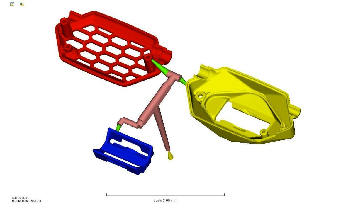
Figure 3: When balancing a runner system to achieve a balanced filling pattern, we want to adjust the runner sizes (Pink sections) not the gate sizes (Green sections).
How Can Simulation Help?
As it has been highlighted above, several different factors need to be considered when optimizing the runner system for a family mold to help ensure a robust processing window and that quality parts will be produced. This can lead to a significant number of iterations of guessing and checking runner sizing to try and get the correct runner dimension. If this step is left to experience or after the mold has been designed the mold design has fewer options to change due to a fixed cavity spacing. This approach is inefficient and usually leads to a suboptimal solution.
Injection molding simulation can help minimize the number of iterations it takes to get to optimize the runner system, by using a Runner Balance Analysis. This type of analysis allows the computer to resize the runners through an automatic algorithm that will yield a more balanced filling pattern for the mold. From the Runner Balance Analysis, the computer will guide the designer to appropriate sizes to help optimize the filling balance between the cavities, and attempt to stay below a target pressure for the mold. From this analysis, the computer can automatically update the runner sizes for your model and get an initial mold filling study performed so you can confirm that the parts can be filled and packed uniformly.
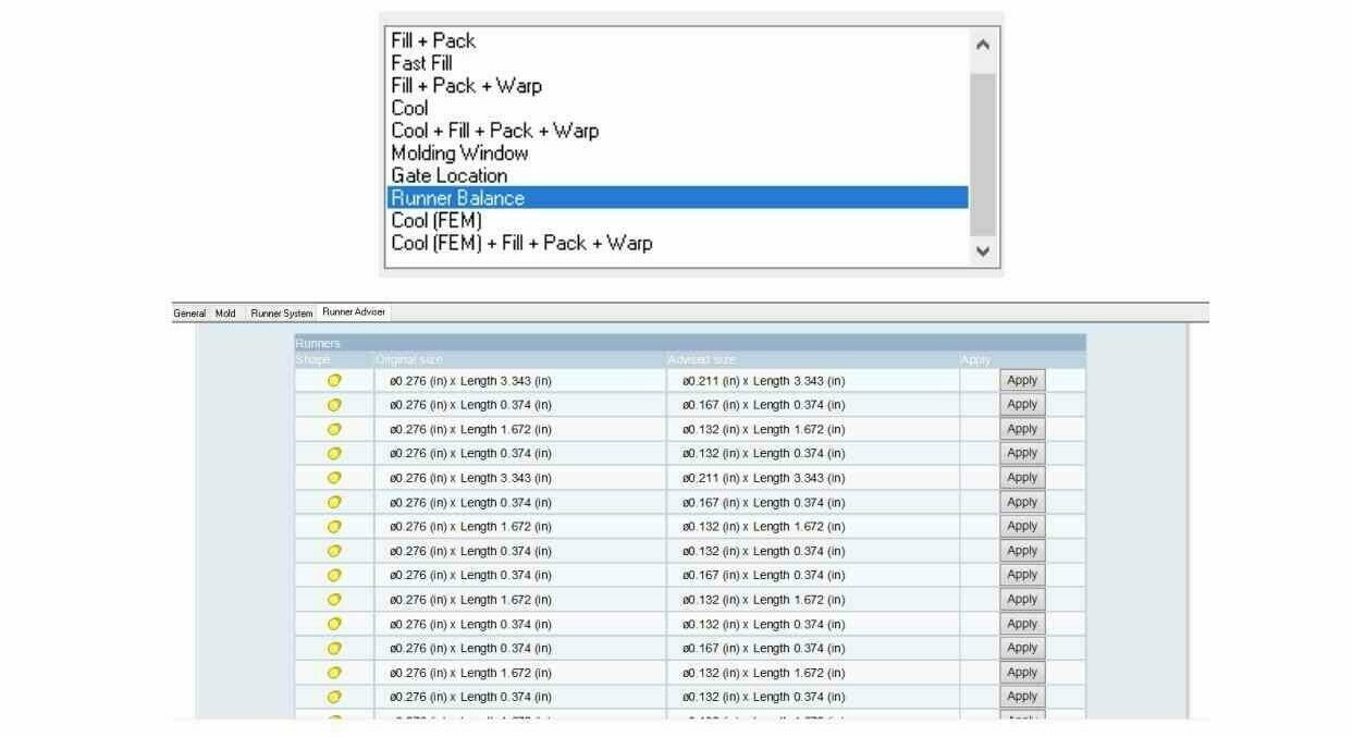
Figure 4: The automated Runner Balancing analysis allows for the software to help size the runner diameters to achieve a balanced filling pattern (Top Image). From the Runner Balance analysis, the analyst can select which changes they want to apply and automatically have the software update the simulation model to be run for a mold filling analysis.
Once the runner balance analysis has been completed and the filling pattern is acceptable, the designer can then extend the analysis to ensure the proposed runner design will allow the parts to be packed out, and will help minimize shrinkage and warpage. By using simulation to help size the runners, and optimize the molding parameters the designer and molder allow for more freedom in the variables that can changed to help yield the highest quality parts. Figure 5 highlight the result of a runner balance analysis, where the optimization of
the runner layout helped create a balanced filling pattern, and helped reduce the injection pressure required to fill the mold by approximately 50%.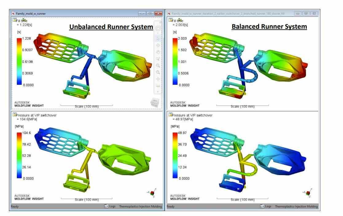
Figure 5: The images above highlight that balancing the runner system can help improve the fill balance between the different cavities that can reduce the required injection pressure to fill the mold and help create a wider process window.